Contributing to Cosmos
Building the Project
For quick instructions, refer to the README. If you’d like more details on the build system, here you go:
Building Documentation
I’ve omited instructions for building docs from the README because they’re all just Markdown, and submitting a PR will trigger a preview build of the site, with documentation, on Vercel. Additionally, if you are using the docker setup, the docs server will be started as well.
To generate docs, install Python 3 and venv then run the following commands:
npm install --include=optional # Make sure optional dependencies are installed
make venv # Creates virtual environment and installs python dependencies.
make keyboards # Generates images of keyboards used in the docs.
npm run doc # Serves the documentation
If you’d like to run the dev servers for the generator and docs simultaneously, use npm run dev:all. Vite is set up to proxy the documentation, so you can go to the main page, click the link to the docs, and view your local changes.
Quickstart, in Detail
The make quickstart command recommended in the README bundles together several useful commands in the Makefile:
npm install --omit=optional # Installs dependencies
mkdir target
make # Compiles protobuf files and expert mode autocompletions
make parts # Generates the mx switch geometry
make keycaps-simple2  # Generates keycaps used for collision detection
make keycaps2 # Generates geometry for all the keycaps
This will set you up for a pretty complete generator. There are a few more commands available for building the production site, which are not included in make quickstart since they require optional dependencies
make keyholes # (requires Java and Leiningen): Generates backwards-compatible Dactyl keyholes
export OPENSCAD=$(which openscad) # For the next 2 commands: sets var to openscad executable
make keycaps-simple # Alternative to make keycaps-simple2; Requires OpenSCAD
make keycaps # Alternative to make keycaps2; Requires OpenSCAD
What’s the difference between keycaps and keycaps2?
The make keycaps-simple2 keycaps2 scripts use a web assembly version of Manifold to render models (and OpenSCAD for running the scripting parts of the scad files), but the translation layer I wrote is not 100% accurate.
The relative proportions of keys are not fully correct, but the scripts are more than good enough for local development.
The make keycaps-simple keycaps scripts are what I use for the production site, but they require a recent version of OpenSCAD (at least 2023) and the Linux version of OpenSCAD seems to struggle rendering the keycaps for some reason. If you wish to use these, either set the OPENSCAD environment variable to the location of the OpenSCAD executable or symlink the executable to target/openscad.
Why so many Make targets?
Everything except make (i.e. running make by itself which triggers the default target) will trigger a script that takes several minutes to execute and depends on too many files to use Make’s dependency system. They’re broken up so that you don’t need to re-run the entire build process if you have, say, only added a new keycap.
You’ll probably find yourself needing to run make (the default target) once in a while, which is intelligent enough to only re-compile things that have changed.
Contributing Guides
Contributing Parts
In the codebase, the part integrated into the keyboard that holds a switch, trackball, screen, etc. is called a socket. Whatever is placed within the socket is called a part. Both the socket and part share the same name, which is used in Expert mode as the type property for a key. This short guide covers adding a new socket & part to the codebase.
If you’re looking for some code to follow along as you complete these steps, you can refer to this Pull Request. It also serves as good reference for when you create a PR of your changes!
- Give the socket a name. The standard I’ve been loosely following is
thing-dimensions-vendor. The vendor & dimensions can be omitted if they are obvious. For example,trackpad-23mm-cirque(I don’t follow my convention) andoled-128x32-0.91in-adafruit. - Edit
src/lib/worker/config.tsand add the name of your socket to the config. You’ll probably be adding it underCuttleBaseKey. - Design a STEP file for the socket. Place it at
src/assets/key-(name).step. If you’re using someone else’s STEP file, make sure it is licensed for reuse. - The boundary of the socket must be a rectangle. Take note of the dimensions. (You can also make it a cylinder—reference the trackpad).
- Edit
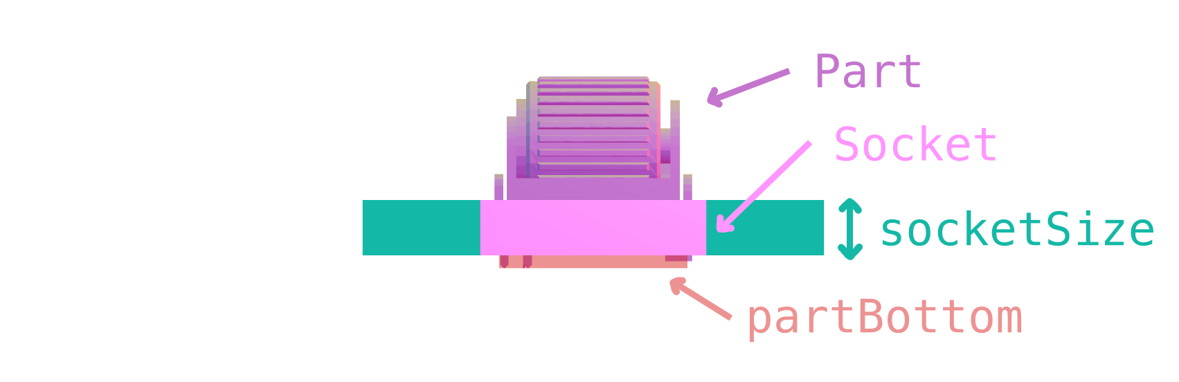
src/lib/geometry/socketsParts.ts. Add your part toPART_NAMESso it can be correctly shown in the BOM. Also editsocketSizeto return the size of the rectangle from step 3. - The
partBottomfunction returns a box describing the boundary of the part that rests in the socket, referenced from the top of the socket. This is used to raise the model high enough so that your part doesn’t collide with the ground! Measure the part and modify this function. - Edit
src/lib/worker/socketsLoader.ts. Import your STEP file and add it toKEY_URLSso the generator can make use of it. - Run
makeagain to regenerate the Typescript type declarations for Expert mode. - Run
make partsto convert the STEP file to GLB so the parts preview page can efficiently display the model.
At this point you should be able to visit http://localhost:5173/parts and see your part’s socket displayed. You’ll also likely have an STL file of the part that goes into the socket. Follow these steps add it:
- Again make sure the STL file is licensed for reuse or that it’s your own. Place it under
src/assets/key-(name).stl. - Edit
src/model_gen/parts.tsso that your STL file can be converted to a GLB. - Edit
src/lib/loaders/parts.tsand add your part. - Re-run
make parts
The working name of Cosmos was Cuttleform, named after the Cuttlefish. Cuttlefish are pretty adaptable!
Contributing Microcontrollers
- Add the microcontroller name to the
SpecificCuttleforminterface insrc/lib/worker/config.ts. There’s no standard for naming yet. - Add configuration for the microcontroller in
src/lib/geometry/microcontrollers.ts. You’ll need to give the microcontroller a nicely formatted name, size (width x height x thickness), bounding box height (set this to about how tall the components stick up from the bottom of the microcontroller), offset (set x and y to zero, and z is set to the distance between the center of the connector & the bottom of the microcontroller), and how far in the cutouts go so that pins are accessible. - Make a model for the microcontroller. You can parametrically generate a board model by editing
src/model_gen/parts.tsthen runmake parts. You don’t need to specify much, since the parametric generator uses the size properties you previously configured. Alternatively, if you have a STL file, you’ll need to convert it to GLB and put it insrc/assets(I use Blender for this).
Using an STL file for a microcontroller?
Follow the following conventions: the board’s short edge is the X axis, the long edge is the Y axis, and the top of the board faces +Z. The board should be centered on the X axis and the side with the connector should be touching the X axis (Y=0), so that most of the board is below the X axis (Y < 0). The bottom of the microcontroller should touching the XY plane. This is illustrated in the screenshot below.
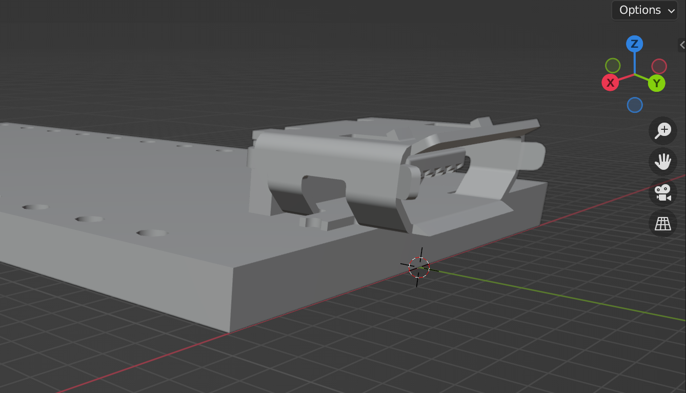
In Blender, make sure to export with “Y axis up” unchecked. GLB files use the convention that the Y axis points up, but in Cosmos the convention is Z points up.
- Edit
src/lib/loaders/boardElement.tsand add the model url toMICROCONTROLLER_URLS. The glb file will be placed intargetorsrc/assetsdepending on whether you autogenerated the board or not. - Edit
src/proto/cuttleform.prototo add the microcontroller to the UI. You’ll also need to editMAP_MICROCONTROLLERinsrc/lib/worker/config.ts. - To auto-assign a specific connector when choosing the microcontroller in basic mode, edit
caseChangeinsrc/routes/beta/lib/editor/VisualEditor.svelte.